Well logging
Well perforation
Well perforation types:
- Wireline/tubing conveyed shaped-charge perforating;
- Drill perforating;
- Setting of isolation explosive packers;
- Torpedoes (well shooting);
- Well stimulation.
Perforating is a process used to create channels in casing, cement and near reservoir for establishing a flow path between near reservoir and wellbore. Shaped-charge or drill perforating is used depending on the borehole conditions and objectives.
Shaped-charge perforating
Shaped-charge perforating became the most common method after the appearance of single-shot perforating systems. Perforating gun OD ranges from 36 mm to 114 mm. Perforating gun can be both wireline and tubing conveyed.
Tubing conveyed perforating has the following advantages:
- Perforation of long intervals at any hole angle within one trip;
- Possibility of underbalanced perforating;
- Various firing head options (drop sub, ball-activated, pressure-activated) depending on the borehole conditions;
- Possibility of swabbing, flow stimulation after firing without POOH of gun (using circulation holes in firing head);
- Possibility of oriented perforating

Oriented perforating
Oriented perforating systems are used to address special geological and technical tasks where formations must be perforated using 0°, 45°, 60°, 90° and 180° phasing and charges must be self-oriented at the required angle relative to the formation interval. Charge tube inside gun carrier is oriented using a special rotation unit.
Tubing perforation
ZKPO-PP-3DK “hole puncher” shaped-charge is used with KPO36 perforating gun to restore circulation between tubing and annulus.
This perforating gun does not damage casing string, which surrounds the tubing. ZKPO-PP-3DK charge does not perforate tubing at maximum distance to tubing but will make up to 3 holes in tubing wall at minimum distance depending on the tubing geometry and strength properties (see figure). At that, the perforating gun must contain minimum six charges with 60° phasing.
Average diameter of hole perforated by ZKPO-PP-3DK charge is:
- Min. 4 mm in Ø 60 mm tubing;
- Min. 3 mm in Ø 73 mm tubing;
- Min. 2 mm in Ø 89 mm tubing (at mud weight max. 1.2 g/cm3)
Drill perforating
Drill perforating is performed in 146mm, 168 mm casing strings using drill perforating gun PS-12 (drill parameters: Ø15 mm, depth 70 mm).
Features and advantages:
- Perforating without impact effect on casing elements;
- Large diameter holes with clean edge;
- Creation of holes in walls of multi-string wells during well works for cementing of annular space;
- Selective perforating of formations represented by alternating permeable and impermeable rocks;
- Perforating of thin oil reservoirs.
Setting of isolation explosive packers
Explosive packer VP
| No | Explosive packer type | Body OD, mm | Casing ID, mm |
| 1 | VP-82 | 82 | 89,0…92,0 |
| 2 | VP-88 | 88 | 96,3…98,3 |
| 3 | VP-92 | 92 | 100,3…102,3 |
| 4 | VP-102 | 102 | 109,0..115,0 |
| 5 | VP-110 | 110 | 117,7…124,0 |
| 6 | VP-118 | 118 | 125,2…133,0 |
| 7 | VP-135 | 135 | 144,0…152,0 |
| 8 | VP-146 | 146 | 156,0…164,0 |
Explosive slip-on packer VPSH
| No | Explosive packer type | Body OD, mm | Casing ID, mm |
| 1 | VPSH-82 | 82 | 88 … 98 |
| 2 | VPSH-88 | 88 | 96 … 104 |
| 3 | VPSH-92 | 92 | 100 … 110 |
| 4 | VPSH-102 | 102 | 109 … 122 |
| 5 | VPSH-110 | 110 | 117 … 124 |
| 6 | VPSH-118 | 118 | 125 … 133 |
| 7 | VPSH-135 | 135 | 144 … 152 |
| 8 | VPSH-146 | 146 | 156 … 164 |
Advantages of explosive slip-on packer VPSH over explosive packer VP:
- Rubber seal cups ensure more reliable setting of isolation packer, even without cementing (depending on casing string condition);
- In addition to rubber cups, packer is provided with extendable cast-iron slips for better engagement with the string;
- rubber cups in these packers are provided with metal support cups on both sides, which prevent rubber flowing into the gap between packer and casing, thus improving sealing.
Recommendations for preparation of wells for setting of explosive packers:
- Quality of packer setting depends on the condition of casing: absence of defects, signs of wear (by tubing collars during tripping and drill pipes during rotation), out-of-roundness, absence of corrosion, buildups on walls.
- Special attention during packer setting must be paid to presence of slurry cake, corrosion, paraffin and other buildups on casing walls. At that, it should be noted that installation of packer in such interval can result in poor isolation, as well as jamming and sticking by the caved slurry cake.
- Packer setting interval must be scraped or reamed and gauged using the gauge of outer diameter not less than outer diameter of the packer.
- In case of paraffin deposits at packer installation depth, scraping should be performed with solvent washing.
- Packer setting depth must be linked to annular cement quality: success is highly probable in case of high-quality annulus cement sheath.
- Packer cannot be installed if casing perforation in setting interval was performed in the past.
- Packer should not be installed at casing joints.
- A 3-5 m cement plug should be additionally installed above the packer to ensure good performance of installed packer.
Torpedoes (well shooting)
Well shooting is performed using special explosive charges (torpedoes). Well shooting objectives are:
- Cutting or breakout of stuck drill pipes/tubing;
- Shaking to release stuck drill pipes/tubing.
Torpedo types:
- detonating cord torpedo (TDSH). Torpedo is run on wireline/inside drill pipe/tubing and intended for shaking/breakout. Torpedo charge size (number of detonating cord threads) and length are determined by downhole conditions and sticking interval;
- demolition torpedo (TSHT and counterparts). Torpedo is run on wireline and intended for cutting stuck drill pipe above sticking depth. Torpedo is sized depending on the downhole conditions and stuck drill pipe parameters;
- Jet torpedo (jet cutter) (TRK and counterparts). Torpedo is run on wireline and intended for cutting stuck tubing above sticking depth. Torpedo is sized depending on the size of stuck tubing;
Demolition torpedo datasheet:
| Parameter | TSHT 20/22 | TSHT 25/28 | TSHT 35/40 | TSHT 43/48 | TSHT 50/55 | TSHT 65/70 | TSHT 84/90 |
| Body OD, mm | 22 | 28 | 40 | 48 | 55 | 70 | 90 |
| Charge diameter, mm | 20 | 25 | 35 | 43 | 50 | 65 | 84 |
| Charge length, mm | 510 | 700 | 700 | 700 | 700 | 500 | 600 |
| Charge weight, kg | 0,255 | 0,55 | 1,08 | 1,62 | 2,2 | 2,65 | 4,91 |
| Length of torpedo and weight, mm | 1780 | 1930 | 1870 | 1870 | 1703 | 1502 | 1682 |
| Torpedo weight, kg | 2,9 | 3,6 | 11,9 | 13,9 | 14,3 | 15,5 | 17,8 |
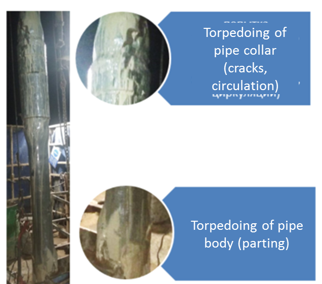
Examples of demolition torpedoing of drill pipe
TSHT-35/40 to body of HWDP 89
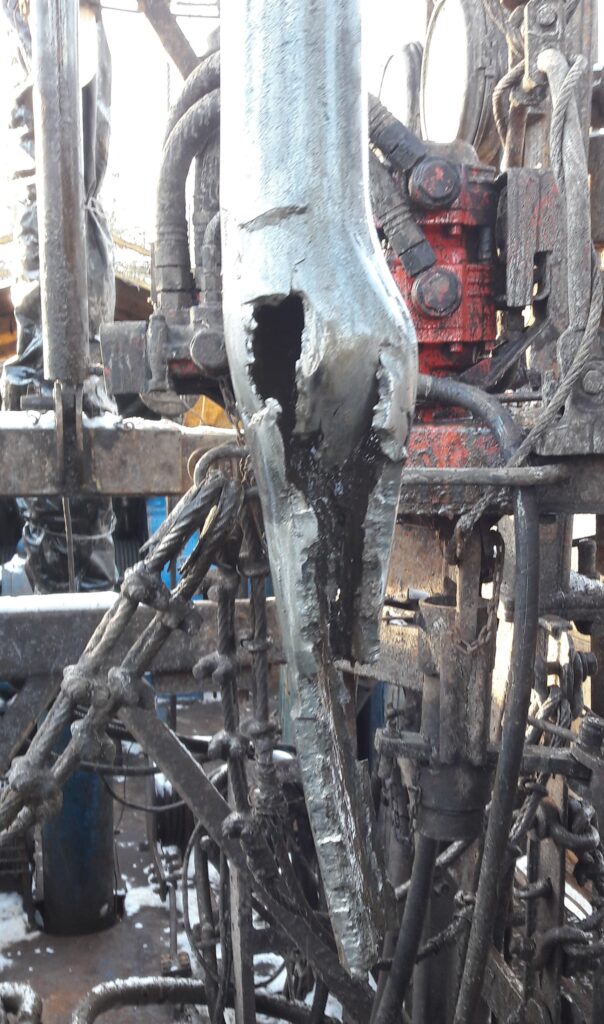
Тайпан Ф-62 по замку и по телу трубы СБТ-114
Jet torpedo datasheet:
| Parameter | TRK45 | TRK55 | TRK68 | TRK75 | TRK85 | TRK90 | TRK110 | TRK118 | TRK135 | TRK146 |
| OD, mm | 44 | 55,2 | 68 | 75 | 85 | 90 | 110 | 118 | 135 | 146 |
| Jet cutter length w/o weight, max. mm | 285 | 321 | 340 | 344 | 344 | 344 | 358 | 358 | 352 | 352 |
| Jet cutter length w/ weight, max. mm | 1255 | 1085 | 1104 | 1108 | 1108 | 1108 | 1122 | 1122 | 1116 | 1116 |
| Jet cutter mass w/o weight, max. kg | 2,4 | 4,5 | 5,5 | 5,8 | 6,1 | 6,2 | 8,1 | 8,3 | 10,4 | 11,0 |
| Weight mass, max. kg | 8,8 | 12,6 | 12,6 | 12,6 | 12,6 | 12,6 | 12,6 | 12,6 | 12,6 | 12,6 |
| Max. allowable hydrostatic pressure, MPa | 70 | 70 | 70 | 60 | 60 | 60 | 50 | 50 | 50 | 50 |
| Maximum allowable temperature, oС | 150 | 150 | 150 | 150 | 150 | 150 | 120 | 120 | 120 | 120 |
| Hold time at maximum allowable parameters, max., h | 1,5 | 1,5 | 1,5 | 1,5 | 1,5 | 1,5 | 1,5 | 1,5 | 1,5 | 1,5 |
| Cut pipe: — OD, mm — maximum wall thickness, mm | 60 5,0 | 73 5,5 | 89 6,5 | 102 6,5 | 114 to 10,0 | 114 to 9,0 | 140 to 10,0 | 146 to 10,0 | 168 to 10,0 | 178 to 10,0 |
| Charge weight: — jet, g — total, g | 11,0 12,3 | 23,0 25,4 | 39,0 42,0 | 60,0 63,0 | 100,0 102,4 | 100,0 102,4 | 240,0 243,0 | 240,0 243,0 | 316,0 318,4 | 316,0 318,4 |
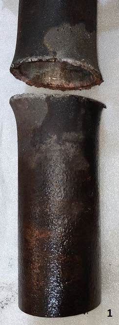
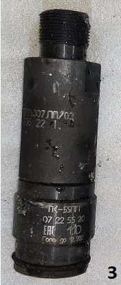
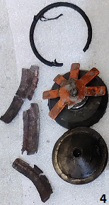
Example of jet torpedoing of tubing body. Bench testing of TK-55PP with tubing 73х7,0
Legend:
1 – Result of torpedoing of tubing 73х7,0;
2 – Jet cutter before shooting;
3 – Jet cutter after shooting (retrieved from well);
4 – Jet cutter segments after shooting (remained downhole).

Well stimulation
Well stimulation is performed using pressure generators, pressure systems developed by Russian top manufacturers: OOO Promperforator, OOO VNIPIvzryvgeofizika, OOO STS-Geoservice.
Perforating gun is selected for specific geologic conditions of the Client based on mathematic calculations and job design.